Are you having trouble getting your sheet metal parts to fit right? You’re not alone. Many designers and engineers struggle with getting the right tolerances in sheet metal fabrication. Understanding tolerances can save you time, money, and frustration by ensuring your parts fit and work like they’re supposed to. Let’s talk about sheet metal tolerance and take the mystery out of this critical part of manufacturing.
Sheet metal tolerance is the amount of variation in dimensions and geometry of fabricated parts that is allowed. It’s important for making sure parts fit together correctly and work like they’re supposed to. Tolerances take into account variations in material properties, manufacturing processes, and equipment capabilities to help maintain quality and performance in finished products.
Tolerances can seem complicated, but they don’t have to be. It’s important to understand the different types of tolerances and how they apply to your project. In this article, we’ll discuss the different types of tolerances, compare sheet metal fabrication to other manufacturing methods, and give you practical tips for managing tolerances in your designs. Whether you’re new to sheet metal or a seasoned professional, this guide will help you navigate the complexities of tolerances with confidence.
What Are the Types of Tolerances in Sheet Metal Fabrication?
Understanding tolerances is the first step to mastering your designs. Here are the main types you need to know:
Dimensional Tolerance
Dimensional tolerance is the allowable variation in linear and angular measurements that ensures your parts fit together properly during assembly.
- Linear Tolerance
This applies to straight-line measurements like the length, width, and height of your part. For example, if a dimension is called out as 10.00 ± 0.01 inches, the actual measurement can range from 9.99 to 10.01 inches.
- Angular Tolerance
This applies to angles and tells you how much the angle can vary in degrees. For example, if an angle is called out as 90° ± 0.5°, the actual angle can range from 89.5° to 90.5°.
Form and Position Tolerance
Form and position tolerances control the shape and orientation of features on your part. These tolerances ensure your parts not only fit together but also function correctly.
• Flatness: Ensures a surface is within a specified flatness tolerance to prevent warping or bending.
• Straightness: Ensures a feature like an edge or axis remains straight within specified limits.
• Parallelism: Ensures two surfaces or features are parallel within specified limits.
• Perpendicularity: Ensures surfaces or features are at right angles to each other within specified limits.
• Circularity: Ensures round features like holes or cylindrical parts are within specified roundness limits.
Surface Roughness
Surface roughness refers to the texture of your part’s surface. It affects the appearance of your part and how it interacts with other parts. Surface roughness is measured in micrometers (µm) and is called out using a roughness average (Ra) value.
What factors affect tolerances in sheet metal fabrication?
Many factors affect the tolerances you can achieve with sheet metal fabrication. Understanding these factors helps you set realistic expectations and design parts that can be made efficiently.
Material Type
Different materials have different properties that affect tolerances. For example, aluminum is softer and more likely to deform compared to steel, which can affect the precision of your cuts and bends.
Material Hardness
Harder materials like stainless steel or titanium typically have tighter tolerances because they resist deformation during cutting and bending. Softer materials like aluminum may require looser tolerances to account for the potential for deformation.
Heat Treatment
Heat treatments after fabrication can change material properties, which can affect tolerances. Designers need to consider how heat treatments will affect the final dimensions of their parts.
Manufacturing Process
The process you use to make a part has a significant impact on the tolerances you can achieve. For example, laser cutting typically has tighter tolerances than stamping because you’re using a laser beam to cut the part.
Sheet Metal Thickness
Thicker sheets of metal tend to have more variation in thickness, which affects tolerances. Thinner sheets are more consistent in thickness, but they are more likely to warp or bend.
Equipment Precision and Capabilities
The precision and capabilities of the equipment you use for fabrication are also critical. Modern CNC machines and laser cutters can achieve very tight tolerances, but older equipment or equipment that is less precise may not be able to achieve the same tolerances.
How Does Sheet Metal Fabrication Compare to Machining and 3D Printing?
Understanding the differences in tolerances between sheet metal fabrication, machining, and 3D printing can help you choose the best method for your project.
Machining
Machining is a subtractive manufacturing process that removes material to create a final geometry. It typically has the tightest tolerances, with a baseline of ±0.005 inches. Machining is great for parts that require high precision and complex geometries.
3D Printing
3D printing is an additive process where you add material layer by layer to create a part. The precision of 3D printing depends on the materials and processes used, with tolerances typically ranging from ±0.002 to ±0.012 inches. 3D printing is great for prototyping and making complex shapes.
Sheet Metal Fabrication
Sheet metal fabrication involves cutting, bending, and forming metal sheets to make your parts. It has looser tolerances compared to machining and 3D printing because of the variability in the processes used. However, sheet metal fabrication is great for making parts with simple geometries and making a lot of them.
| Category | Specification | Description |
|---|---|---|
| General Tolerance Guidelines | .XX: ±0.01 in. | Standard tolerance for two decimal places measurements |
| .XXX: ±0.005 in. | Standard tolerance for three decimal places measurements | |
| .XXXX: ±0.0005 in. | Standard tolerance for four decimal places measurements | |
| Angles: ± 0.5° | Standard tolerance for angular measurements | |
| Material Thickness Variations | 16 gauge cold-rolled steel | Stated thickness: 0.057 in., Actual thickness: 0.056 in. |
| Precision Levels | Machining | Baseline tolerance: ±0.005 in. |
| 3D Printing | Tolerances: ±0.002 in. to ±0.012 in. (±0.051mm to 0.305mm) | |
| Sheet Metal Fabrication | Looser tolerances due to variability in processes | |
| Manufacturing Processes | Laser Cutting | Tolerances down to ±0.002 in. |
| Punching | Standard tolerances of ±0.005 in. | |
| Bending/Forming | Tolerances typically ±0.010 in. bend to edge and ±0.02 in. bend to bend, with a maximum cumulative tolerance of ±0.03 in. |
What Are Premium Sheet Metal Tolerances?
At Premium Rapid & Mold, we strive to hit the tight tolerance standards required for precision sheet metal parts. Our general tolerance guidelines are:
- .XX: ±0.01 in.
- .XXX: ±0.005 in.
- .XXXX: ±0.0005 in.
- Angles: ± 0.5°
Tolerances on One Surface
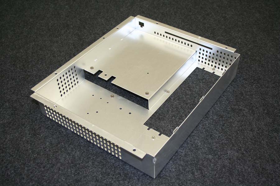
The tolerances on one surface are typically tighter because you’re creating the features with one machine, like a laser or a punch. This allows you to maintain control similar to what you get with machining and 3D printing.
Tolerances Across Multiple Surfaces
When you get into parts that involve multiple bends and surfaces, the tolerances become looser due to the variability introduced by each process. For example, a linear tolerance of ±0.030 inches and a stacking angular tolerance of 1° per bend are standard for those types of parts.

Demystifying Precision Sheet Metal Tolerances
Raw Materials
Sheet stock often runs thinner than the stated gauge thickness. For example, 16-gauge cold-rolled steel might have a stated thickness of 0.057 inches but an actual thickness of 0.056 inches. You need to take this into account when you specify your tolerances.
Manufacturing Processes
Different processes give you different levels of precision:
• Laser Cutting: You can get tight tolerances down to ±0.002 inches for features on the same surface.
• Punching: You’ll get standard tolerances of ±0.005 inches for features on the same surface.
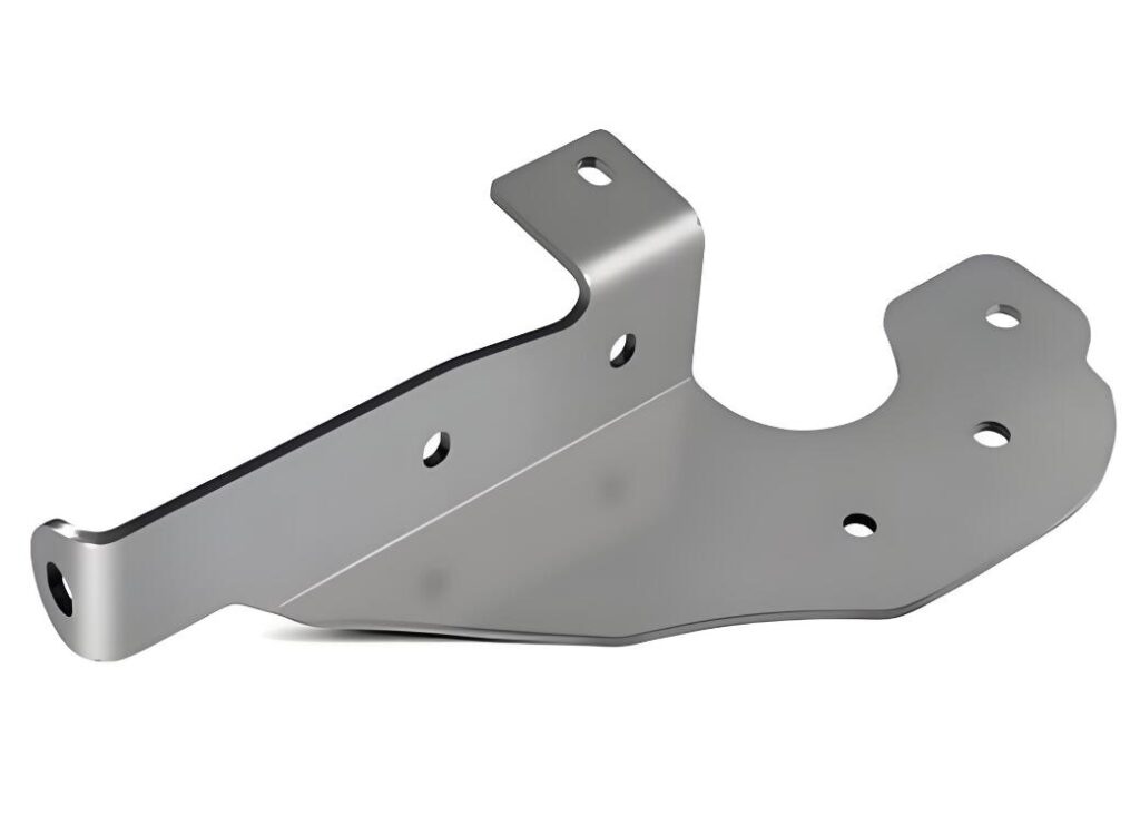
• Bending/Forming: You have looser tolerances because the material stretches. Typically, you’ll need a tolerance of ±0.010 inches bend to edge and ±0.020 inches bend to bend, with a maximum cumulative tolerance of ±0.030 inches.
The Stacking Struggle
Case Study 1: Automotive Bracket
Part: Engine Mount Bracket
Situation: A manufacturer needed a precision engine mount bracket made from sheet metal. The bracket needed to be very accurate dimensionally so it would fit in the engine assembly and withstand a lot of stress and vibration.
Challenges:
Material: The bracket was made from high-strength steel, which is hard to work with and hard to hold tight tolerances on.
Complex Geometry: The bracket had a lot of bends and mounting holes that needed to be aligned properly.
Stress and Vibration: The bracket had to hold up under a lot of stress and vibration, so we had to be very careful with quality control.
Solutions:
Laser Cutting: We used laser cutting to do the initial cuts to get the mounting holes within ±0.005 inches.
Precision Bending: We used advanced CNC bending machines to make sure the bends were accurate within ±0.010 inches.
Quality Control: We had a lot of quality control steps, including using a coordinate measuring machine (CMM) to check the tolerances, to make sure the bracket was made correctly.
Result: We were able to make the engine mount brackets and hold all the tolerances, so they fit in the engine assembly and held up under the stress and vibration.

Case Study 2: Medical Device Enclosure
Part: Enclosure for a Medical Diagnostic Device
Situation:
A medical device manufacturer needed a sheet metal enclosure for a diagnostic device. The enclosure had to meet strict regulatory standards and be safe and reliable for the device.
Challenges:
Material: The enclosure was made from stainless steel, which had to resist corrosion and be durable.
Surface Finish: The enclosure needed a good surface finish to be clean and hygienic, with a roughness average (Ra) of less than 0.8 µm.
Precision Fit: The enclosure had to hold some sensitive electronic components, so the cutouts and bends had to be very accurate.

A Note on Tolerance Stack-Ups
At Premium Rapid & Mold, we have a lot of experience, and we anticipate and mitigate tolerance stack-up issues before they happen. If they do happen, we have other solutions like floating fasteners or secondary machining operations. These strategies help us complete your project successfully while also managing your tolerances effectively.
Tolerance Takeaways
Understanding and managing tolerances is crucial to getting quality and performance in your sheet metal parts. Here are some takeaways:
• Precision Varies Across Methods: Different methods have different levels of precision. You need to choose the right method based on what you’re trying to do.
• Thoughtful Design: Design guidelines and planning can help you get great results with your sheet metal parts.
• Experienced Manufacturers: If you work with experienced manufacturers like Premium Rapid & Mold, they can help you manage your tolerances and give you great parts

Precision Sheet Metal Tolerance FAQ
Why is tolerancing in precision sheet metal fabrication more complex than in precision machining?
Tolerancing in precision sheet metal fabrication is more complex because of variations in raw materials and manufacturing processes. When you precision machine something, you start with a solid piece of material. In precision sheet metal fabrication, you start with sheet stock that has inherent thickness variations. Plus, the forming processes have specific tolerancing constraints.
What are the variations in sheet metal thickness, and how does it affect tolerancing?
Sheet metal thickness often varies from its stated gauge. For example, a 16-gauge cold-rolled steel sheet might have a stated thickness of 0.057 inches but an actual thickness of 0.056 inches. These thickness variations consume a portion of the allowable tolerance, which affects the final dimensions of your part.
How do different manufacturing processes affect tolerances in sheet metal fabrication?
The manufacturing process used for specific features affects tolerances. Features on the same surface can achieve standard tolerances of ±0.005 inches. Formed features like flanges require looser tolerances because the material stretches during forming. For example, flanges typically need a tolerance of ±0.010 inches bend to edge.
What are tolerance stack-ups, and how are they managed in precision sheet metal fabrication?
Tolerance stack-ups occur when multiple features with individual tolerances come together in a part. At Premium, we have a lot of experience in this area and use strategies like floating fasteners or secondary machining operations to anticipate and mitigate tolerance stack-up issues. These methods help us complete your project successfully while also managing your tolerances effectively.
Can tighter tolerances be achieved in sheet metal fabrication, and what are the trade-offs?
Yes, you can achieve tighter tolerances by using secondary machining operations or other processes. When you do this, you will have tighter tolerances, but the cost will be higher because you are adding machine time. When you are choosing your fabrication methods, you need to balance your desired tolerances with your cost considerations.
Conclusion
Tolerances are a big deal when it comes to your sheet metal parts. If you don’t understand the different types of tolerances, what affects them, and how to manage tolerance stack-ups, your parts are not going to meet your expectations. If you want to get the best results, you need to understand tolerances and how to work with them. It’s a great way to get what you want and need. If you want to get even better results, work with a company like Premium Rapid & Mold that’s been doing this for a long time. They can help you get the best tolerances possible and great parts.

