
Are you frustrated with high production costs and design errors on your sheet metal parts? This is a common problem that affects your efficiency and the quality of your products. But don’t worry, I’ve got you covered! You can solve this problem by optimizing your sheet metal designs for manufacturability. This will help you reduce errors, lower costs, and improve the overall quality of your products.
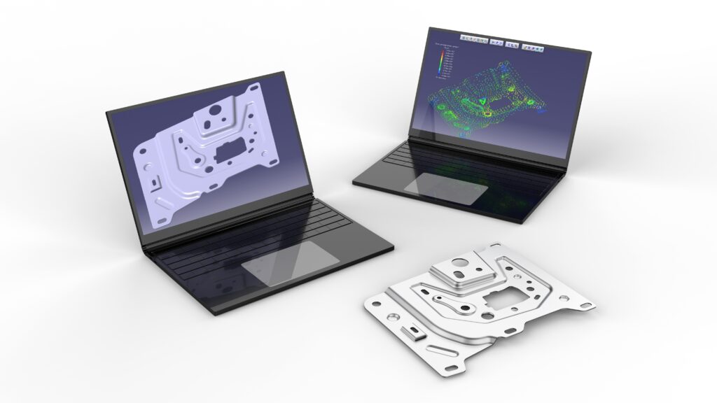
To optimize your sheet metal designs for manufacturability, you need to design them using Design for Manufacturability (DFM) principles. These principles include selecting the right materials, using standard hole sizes and bend radii, maintaining proper clearances, and considering the capabilities of the manufacturing process. It’s also important to simplify your designs and make sure you have enough space between features.
It’s important to understand what makes a design manufacturable. This includes not just the design itself but also how you’re going to make it. Let me share some key tips and guidelines to help you create sheet metal designs that are easy to manufacture, cost-effective, and high-quality.
What is Sheet Metal?
Sheet metal is a versatile material that can be found in an endless number of applications. It is made from various metals such as aluminum, brass, titanium, nickel, tin, and copper that have been processed into thin, flat pieces. These thin, flat pieces can be turned into foils, leaves, or plates. Because it is light, strong, and elastic, sheet metal is used across numerous industries, from automotive to consumer electronics.
What is DFM for Sheet Metal?
DFM for sheet metal is a series of engineering practices designed to make the manufacturing process easier and cheaper by designing parts that are easy to manufacture. This means considering the limitations and capabilities of the manufacturing process as you design the part. The main goals of DFM are to reduce the time it takes to produce parts, reduce the amount of waste, and ensure that you produce quality parts.
Key Principles of DFM for Sheet Metal
- Select the Right Material: Choose the material that makes the most sense for the application and the manufacturing process.
- Standardize: Use standard sizes and features to make the manufacturing process more straightforward and cheaper.
- Keep It Simple: Try to make the part as simple as possible so that it requires the fewest number of manufacturing steps and has the least number of chances for errors.
- Manage Tolerances: Make sure that the tolerances that you are asking for can be achieved and don’t make manufacturing the part more difficult.
- Choose the Right Process: Design parts that take advantage of the capabilities of the manufacturing processes that you have available.

Why is Design for Manufacturability (DFM) Important?
DFM is important because it helps bridge the gap between design and production. By designing for manufacturability, you can avoid technical problems, reduce lead times, and save money. The ultimate goal is to design parts that are easy to manufacture and don’t sacrifice quality.
Basic Sheet Metal Operations
It’s essential to understand the common operations in sheet metal fabrication to design effectively.
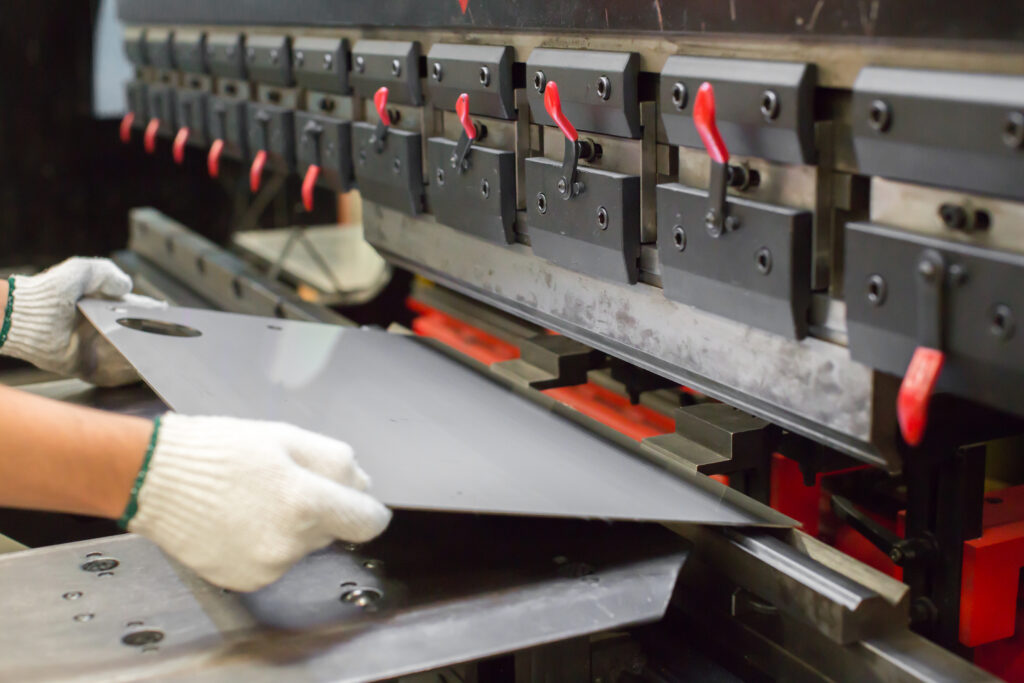
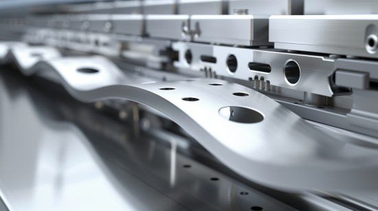
Bending
Bending is the process of deforming a sheet metal workpiece around a straight axis. You use tools like brake presses to bend sheet metal. It is critical that you use the correct bend radii and bend allowances to avoid material failure and to ensure accuracy.
Drawing
Drawing, or deep drawing, is a process where sheet metal is stretched into hollow shapes. You see this in things like soda cans and automotive components. The process uses a punch and die setup to create the desired shapes.
Shearing
Shearing cuts the workpiece using a punch. It is different from forming processes and is used to cut sheet metal into the desired shape or size.
Miscellaneous Processes
• Spinning: Shapes metal by pushing it over a rotating mandrel.
• Stretch Forming: Involves stretching and bending sheet metal to create contoured shapes.
• Embossing: Creates raised surfaces or lettering on sheet metal.
• Coining: Combines sizing and embossing processes to shape ductile metals.
• Trimming: Removes burrs and smooths cut edges.
• Piercing: Uses a sharp punch to make holes.
• Punching: Creates circular holes using a punch and die.
• Blanking: Cuts shapes from strips, creating pieces called blanks.
Other Operations
• Laser Cutting: Uses a laser to cut precise shapes in the metal, providing high accuracy and smooth edges.
• Waterjet Cutting: Uses a high-pressure jet of water mixed with abrasive particles to cut through metal without generating heat.
• Roll Forming: Bends a long strip of sheet metal into a desired cross-section by passing it through a series of rolls.
• Hydroforming: Uses high-pressure hydraulic fluid to press room temperature working material into a die, making it suitable for complex shapes.

DFM Guidelines for Sheet Metal Design
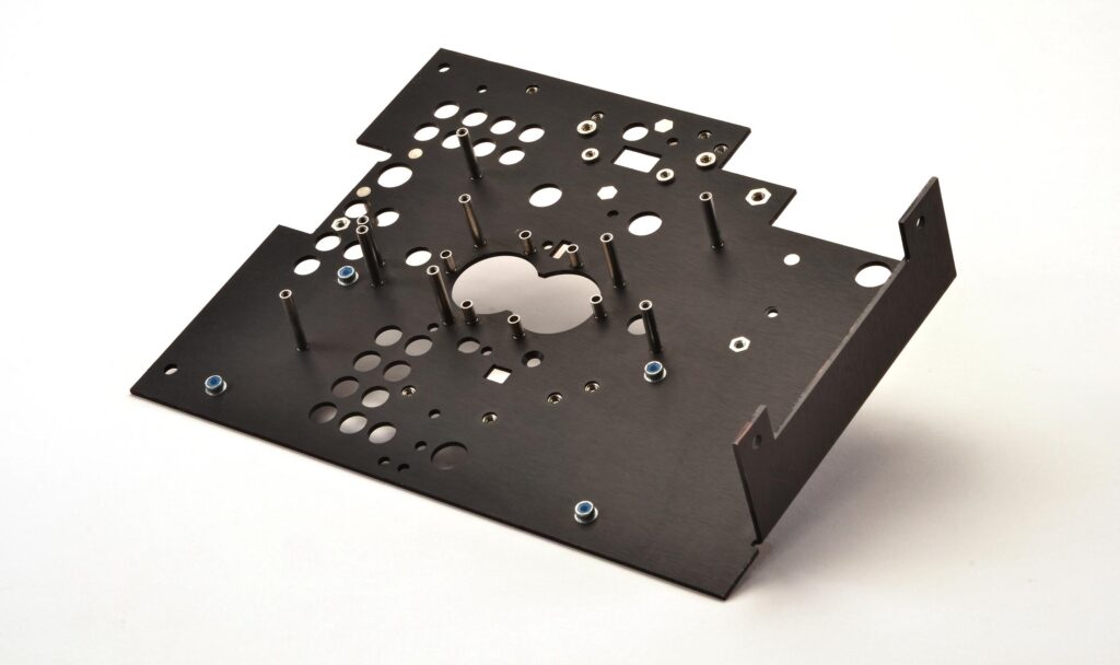
Hole Design
• Diameter: Make sure hole diameters are larger than the material thickness to avoid breaking the tool.
• Distance Between Holes: Keep at least two times the material thickness between holes to avoid distortion.
• Distance from Edge: Keep holes at least the material thickness away from the edge to avoid weakening the material.
• Hole to Bend Clearance: Keep at least 1.5 times the material thickness between holes and bends to avoid distortion.
Bend Design
• Minimum Bend Radius: Use a minimum bend radius based on the material and tooling to ensure good, clean bends.
• Bend Relief: Use bend reliefs to avoid tearing and for good bending.
• Flange Width: The minimum flange width should be four times the material thickness for strength and looks.
Additional Guidelines
• Avoid Sharp Corners: Sharp corners can create stress concentrations and are difficult to make. Use rounded corners wherever possible.
• Consistent Material Thickness: Make parts with consistent material thickness to make them easier to manufacture.
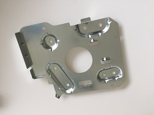
• Tab and Slot Design: Use tabs and slots for easy assembly and added strength.
• Welding Considerations: Make parts with welding in mind, ensuring that you have good access for welding tools and avoiding complex weld paths.
• Standard Fasteners: Use standard sizes and types of fasteners to make assembly easier and cheaper.
Benefits of DFM
DFM is a strategic way to improve the quality of your product while reducing the cost to produce it. The benefits of DFM include:
• Cost-Effectiveness: Saves you money on material and the cost to produce the part.
• Less Labor: Simplifies the manufacturing process and requires less labor.
• High Quality: Standardizes the design for consistent, high-quality parts.
• Happy Customers: Ensures your product will work and will be delivered on time.
• Faster Development: Makes it easier to go from design to production.
• Easier Design: Standardizes the part for easier manufacturing.
• Less Waste: Reduces the amount of material you waste and makes sure you use what you have.
• Reliable: Ensures your product will work as it should and will not fail.
• More Flexible: Makes it easier to change and modify designs during the design process.
Mistakes to Avoid in Sheet Metal Design
To create a successful sheet metal design, avoid these common mistakes:
- 3D Models Without Bends: Always show the bends in your 3D models to represent how the part will be made.
- Sharp Corners: Avoid 90-degree, sharp corners that can cause stress concentrations.
- Features Near Bend Lines: Don’t put features too close to bend lines that will cause distortion.
- Don’t Do Your Homework: Make sure you pick the right flat pattern and material for your design.
- Choose the Wrong Fabrication Type: Pick the right way to make the part.
- No Details: Make sure you put the right details into your CAD design based on the thickness chart.
- Unrealistic Welding Requirements: Make sure your welding requirements are practical and can be achieved.
- Strength of Material: Make sure you understand the strength requirements, especially for U-channels and structural components.
Sheet Metal Prototyping
Sheet metal prototyping is the process of making a model of a metal part that you can test and try out before you make it in large quantities. Here are some ways to prototype sheet metal parts:
• Precision Prototype Metal Stamping: Use a stamping press to make very high-precision parts.
• Rapid Prototyping: Make models using 3D virtual drawings.
• Incremental Sheet Metal Forming: Use a mill to form parts without a die.
Specialized Points in Sheet Metal Design
Tolerancing
• Consistent Tolerances: Use the same tolerances on the same features to make sure everything looks thesame in production.
• Loose Tolerances Where Possible: Make the tolerances bigger on things that don’t matter to save money and make more parts.
Grain Direction
• Think About Grain Direction: The grain direction of the sheet metal will affect how strong and flexible the part is. Make sure your features and bends line up with the grain to get the most strength.
Springback Compensation
• Think About Springback: When you bend metal, it springs back a little bit. You need to account for this springback when you design the angle to get the right final shape.
Tab and Slot Design
• Interlocking Parts: Use tabs and slots to make it easy to put parts together and to make the part stronger. This also helps you put parts in the right place when you weld or fasten them together.
Edge Treatment
• Deburring: Always take the burrs off the edges to make it safe to handle and easier to put together.
• Hemming: Think about hemming edges to make them stronger and to keep them from being sharp, especially on things people will touch.
Finishing Techniques
• Anodizing: Makes the part resistant to rust and makes the surface harder. This is most often done on aluminum parts.
• Powder Coating: Puts a tough finish on the part that looks good and is good for all types of parts.
• Plating: Puts a layer of metal, like chrome or nickel, on the part to make it wear better and look good.
Tool and Die Design
• Special Tools: Spend the money to get custom tools and dies that make the parts just the way you need them. This will help you make parts that are very precise and make the most of your time.
• Keep Tools Sharp: Keep your tools in good shape to avoid making bad parts and to keep the quality up.
Surface Flatness and Straightness
• Flatness Control: Make sure the parts are flat so they go together right. You can do this by how you roll the metal or by how you level it out.
• Straightness: Keep the parts straight, especially if they are long, so they fit right and work right.
Heat Treatment
• Stress Relief: Use heat to take the stress out of the part after you form it and cut it.
• Annealing: Use heat to make the parts soft again if you have bent them a lot.
Fastening Techniques
• Self-clinching Fasteners: Use nuts and studs that clinch themselves to the part so they stay there forever in thin sheet metal.
• Riveting: Use rivets in parts that need to be strong and stay together.
Advanced Joining Techniques
• Laser Welding: Use lasers to weld parts together very precisely and strongly, especially if you don’t want to heat up the part.
• Adhesive Bonding: Use glue to keep parts together that need to look good or that can’t be welded.
Conclusion
Designing sheet metal parts that are easy to make involves thinking about what you are doing. By following the rules of DFM, understanding how sheet metal is made, and not making the same mistakes I do, you can design parts that are easy to make and good quality. Making sure you pick the right material, paying attention to the design, and being careful in how you make the parts are all important to making successful sheet metal parts.